Welcome to my blog,www.obd2tool.com.

Search site
Contact
Car diagnostic tools information by obd2tool
https://www.obd2tool.com
Welcome to my blog,here some auto diagnostic tools will be displayed. If you want to know more information,you can visit our official website: www.obd2tool.com.
News
Visitors notice
12/01/2014 07:47Website launched
12/01/2014 07:46The blog of OBD2 TOOL
How To Use Tech 2 For Service Programming System
05/05/2020 18:04VXDIAG Porsche PIWIS Tester III Software Update to V38.900
04/08/2020 16:37The best Tool to Program BMW Rubber Remote Key Fob
02/21/2020 18:43FREE Caterpillar ET-2019C (Select Level), Diagnostic Software for Caterpillar Engines
02/21/2020 18:39Nissan Sentra 2014 Steering Angle Sensor Adjustment by Launch X431 Torque
01/31/2020 20:57Launch X431 Throttle Set FRE Memory for Nissan Maxima 2017
01/31/2020 20:55Mercedes W204 All Keys Lost by Autel IM608 + GBOX + XP400 Read Password
01/24/2020 06:01How to Use Autel MaxiIM 608 to Detect Vehicle Remote
01/05/2020 15:59Read BMW EDC17C50 ISN Code from DDE using Autel IM608 & G Box
12/22/2019 16:23Where To Get MB Star C4 Star Diagnosis Dealer Level SD Connect Multiplexer
12/05/2019 11:52wiTECH 2.0 Will Not Communicate With Any Modules – All Modules Are Red
Theory of Operation:
Below are few different ways communication on a vehicle takes place:
* Scan tool to the Central Gateway Module (Ex: SGW, TIPM, BCM, etc.)
* Module to Module
* Module to Device
* Device to Module
Communication to the vehicle is established with a scan tool, through the Data Link Connector (DLC) to the Central GateWay Module (CGW) over the Controller Area Network (CAN) Bus.
On this vehicle the Body Control Module (BCM) is the CGW between the high and low speed CAN Bus networks (CAN-C and CAN-IHS); and communicates with the scan tool through CAN C.
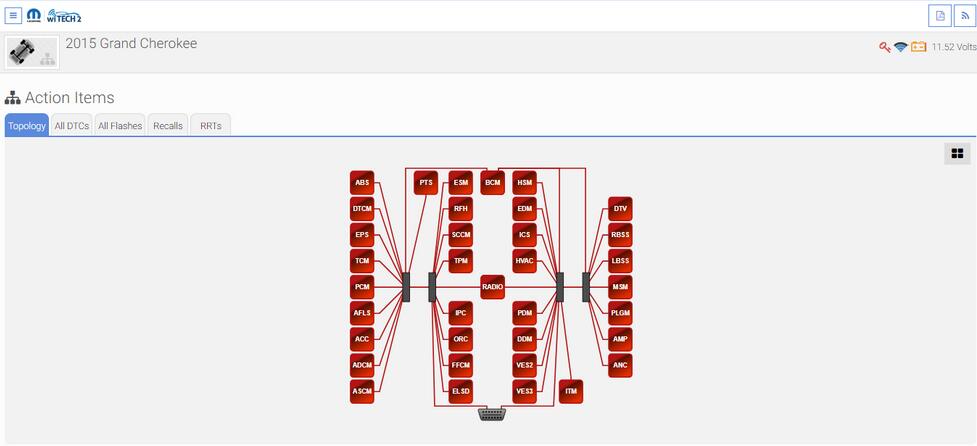
The witech 2.0 Bus architecture of this vehicle operates in a “hub” or “star” style, meaning all of the modules are connected at a central point in the Star Connectors. The terminating resistors for CAN Bus are located in the Star Connectors that are part of the body and instrument panel wiring harnesses. In other CAN Bus architectures a vehicle may operate in a “stub” or “backbone” style, meaning there is a single, main line that connects all modules. The terminating resistors for CAN Bus in the “stub” or “backbone” style are located in 2 separate dominant modules that are placed as far apart as is physically possible. The scan tool becomes another module on the vehicle’s networks by acting as the Master Module of all Bus networks while connected to the DLC and contributes voltage to the operation of the CAN Bus.
The following vehicle interactions listed below will aid in predetermining the type of vehicle communication that is/isn’t available:
NOTE: If the Hazard Lamps and Headlamps are active, this indicates the BCM is functioning and is most likely not the cause of the CAN Bus fault.
* Operating the Lock/Unlock button of the FOB with Integrated Key (FOBIK) – When any one of the Remote Keyless Entry (RKE) transmitter buttons of the FOBIK are depressed, the onboard transmitter generates a high frequency RF request signal that is received and validated by the Radio Frequency Hub Module (RF Hub). If the RF Hub determines the RKE transmitter RF request signal was generated by a FOBIK that is valid for the vehicle, the RF Hub relays electronic request messages to the BCM over the CAN BUS to invoke the functions or features associated with the request.
* Opening a Door – The Door Latches contain Ajar Switches that are hardwired to the BCM. The status of the Door Ajar Switch Sense circuit input is monitored by the BCM, which then sends the proper electronic message to other modules in the vehicle over the CAN Bus.
* Turning the Headlights on – The Headlamp switch uses a single resistor multiplexed output to control the many functions and features it provides. The switch receives a clean ground from the BCM on a Headlamp Switch Multiplex (MUX) Return circuit. The BCM then reads the switch outputs using an internal pull up on the Headlamp/Fog Lamp Switch Signal circuit to control the exterior lighting functions
* Turning the Hazard Lamps on – The status of the Hazard Switch is continually monitored by the circuitry within the Instrument Panel Switch Bank in the Integrated Center Stack (ICS). The switch receives battery voltage at all times through a Fused Battery Feed circuit, and a path to ground at all times through the Instrument Panel wire harness. Whenever the Hazard Switch is in its latched and lowered position, the hazard warning system is selected and the switch bank circuitry provides a hardwired output to the BCM. When the BCM receives a Hazard Switch input, it then controls hazard warning system operation and flash rate by controlling battery voltage outputs through high side drivers on the Right and Left / Front and Rear Turn Signal Feed circuits.
* Honking the Horn – Each Horn has a path to ground at all times through its wire harness connection to an eyelet terminal secured to the body sheet metal. The Horns are controlled by a Fused B(+) output received through a relay within the front Power Distribution Center (PDC) Assembly and controlled by the BCM.
During an ignition cycle, the Auto Scanner Tool CAN C Bus network may go into default mode when communication has been hindered with the BCM. In some situations, when this happens the wipers automatically operate in a delay mode and the Headlamps are activated by the BCM. When the ignition is turned off, the vehicle will exit the default mode and operation of the Wipers and Headlamps will stop. When turning the ignition on again, if the CAN C Bus fault is still present, the vehicle will exhibit a no crank, no start condition; and no scan tool communication response to the vehicle.
Possible Causes:
* INOPERATIVE SCAN TOOL
* MANUALLY SELECTING THE INCORRECT YEAR AND/OR MODEL WITH WITECH 2.0
* DATA LINK CONNECTOR (DLC)
* DATA LINK CONNECTOR FUSED B (+) CIRCUIT OPEN OR HIGH RESISTANCE
* DATA LINK CONNECTOR GROUND CIRCUIT OPEN OR HIGH RESISTANCE
* CAN C (+) BUS CIRCUIT OPEN, SHORTED OR HIGH RESISTANCE
* CAN C (-) BUS CIRCUIT OPEN, SHORTED OR HIGH RESISTANCE
* POOR TERMINAL CONTACT OR CONNECTOR CONNECTION(S)
* STAR CONNECTOR
* ANY MODULE ON THE CAN C BUS
NORMAL CAN C BUS CIRCUIT VOLTAGE TABLE
* CAN C BUS LOW (-) : 1.5 – 2.5 volts
* CAN C BUS HIGH (+) : 2.5 – 3.5 volts
* Difference Between CAN C BUS (+) and CAN C BUS (-) : 0.5 volt
* CAN B or IHS BUS LOW (-) : 1.5 – 2.5 volts
* CAN B or IHS BUS HIGH (+) : 2.5 – 3.5 volts
* Difference Between CAN B or IHS BUS (+) and CAN B or IHS BUS (-) : 0.5 volt
* CAN C1 or C2 BUS LOW (-) : 1.5 – 2.5 volts
* CAN C1 or C2 BUS HIGH (+) : 2.5 – 3.5 volts
* Difference Between CAN C1 or C2 BUS (+) and CAN C1 or C2 BUS (-) : 0.5 volt
https://obd2lily.livedoor.blog/archives/10997122.html